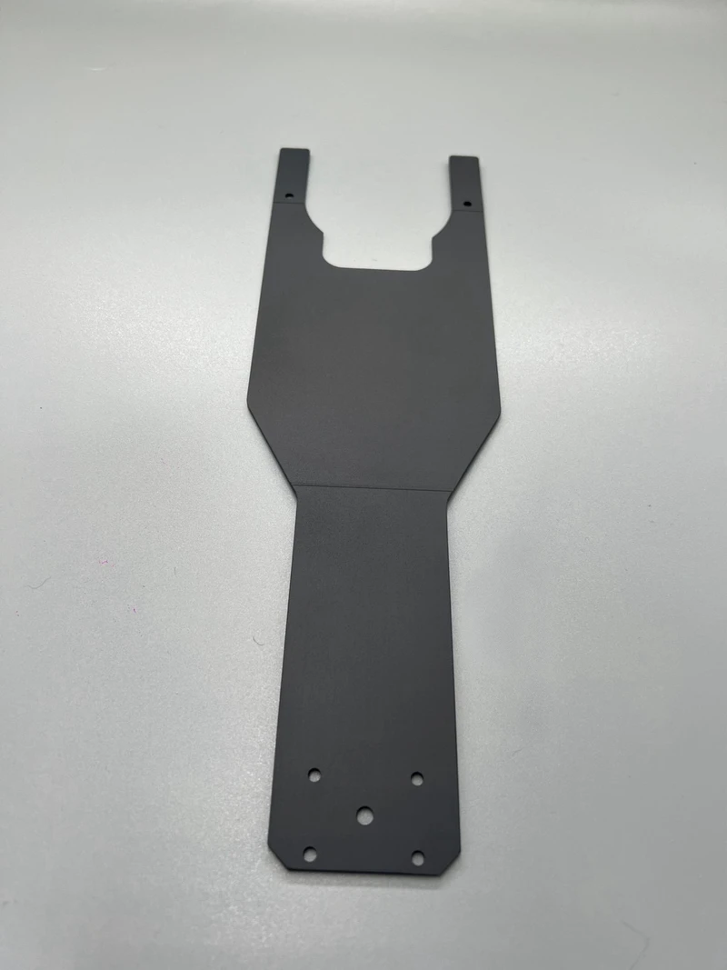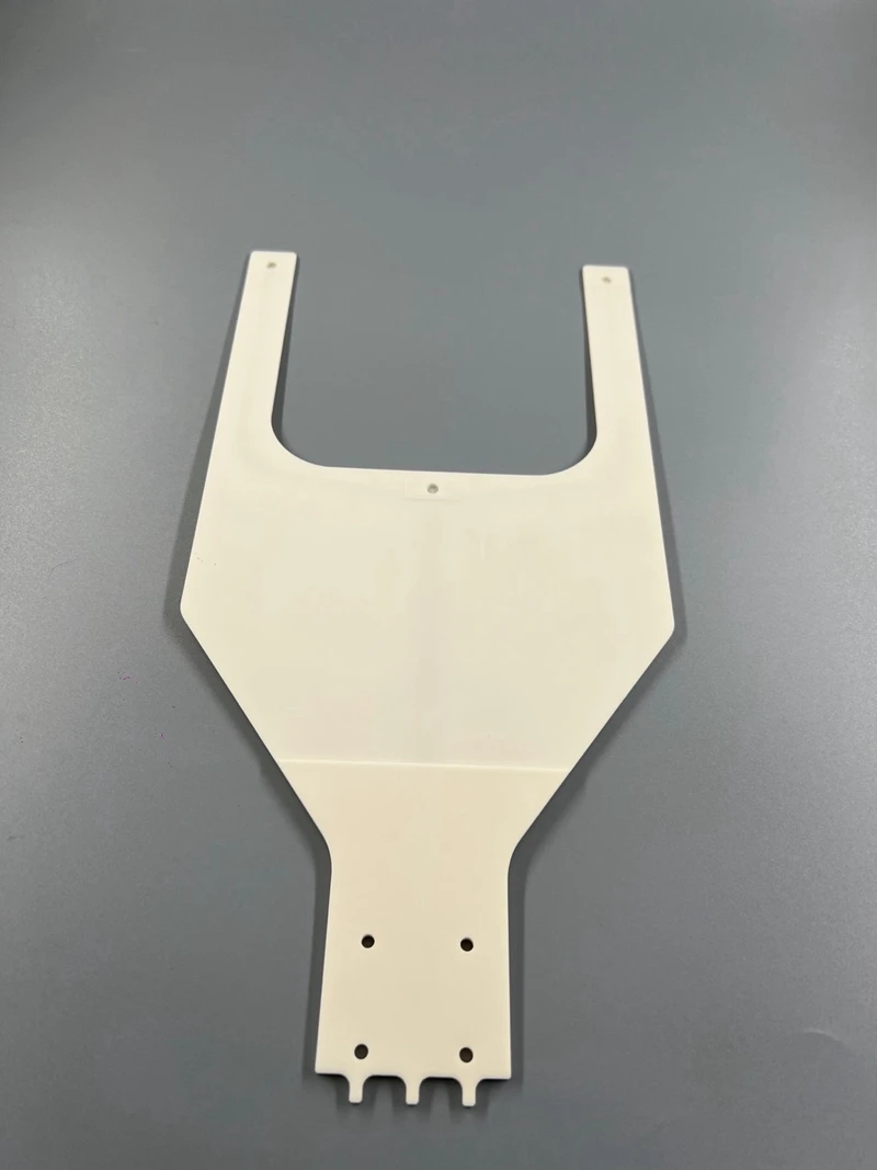
Wafer End Effector

LONGYI · CERAMIC WAFER HANDLING · MADE IN TAIWAN

Ceramic End Effector (Wafer End Effector) – Custom Alumina & SiC

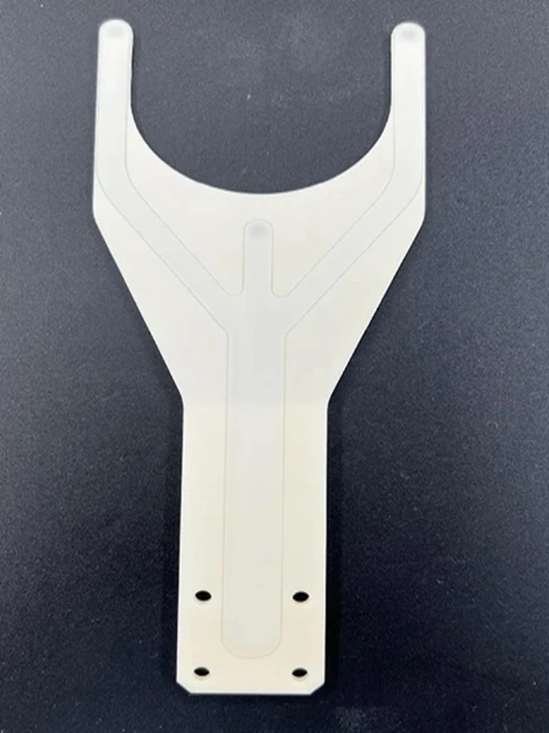
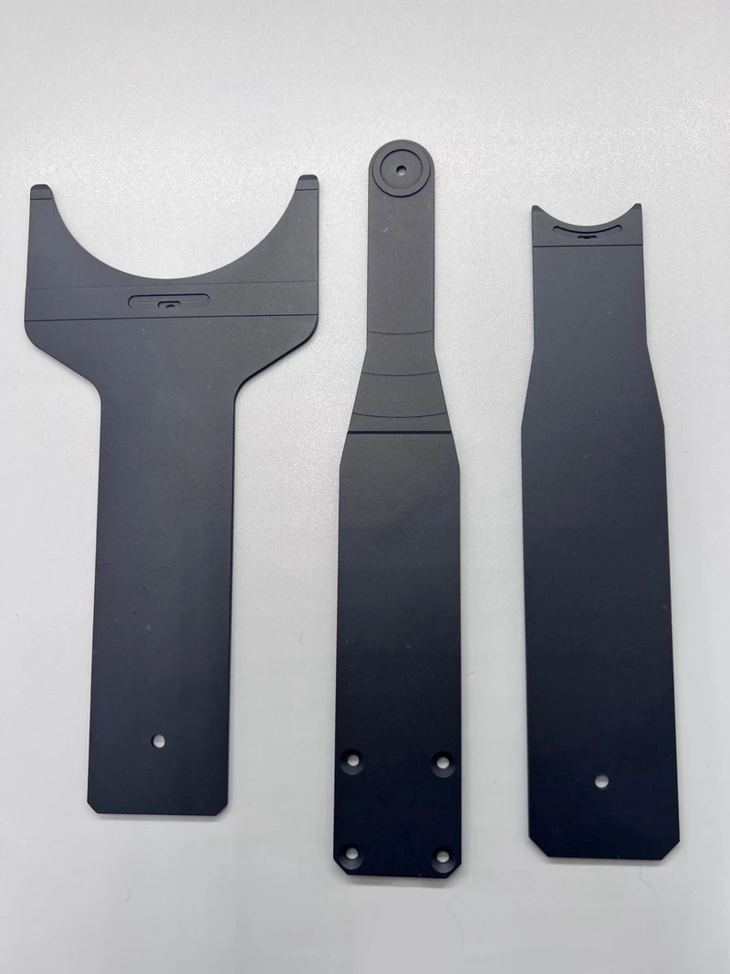
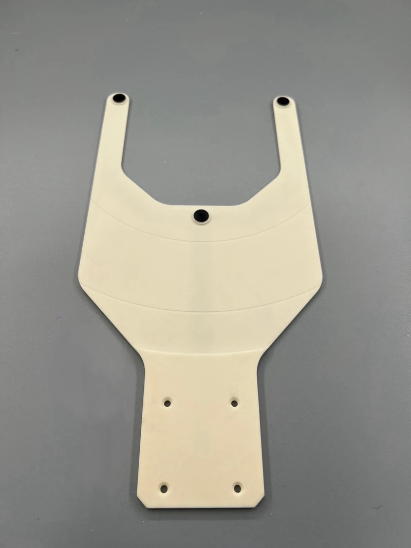
A ceramic end effector is the blade or fork at the tip of a wafer transfer robot — the only part that touches the wafer, so it decides how much particle, breakage and placement error the tool generates. LONGYI is a Taiwan manufacturer of ceramic wafer end effectors in Alumina, Silicon Carbide and Anti-Static Ceramic, from sintering to the lapped, measured part — built to your drawing or reverse-engineered from a sample. OEM and ODM.

QUICK ANSWER

A ceramic end effector (wafer end effector) is a precision robot blade — typically 1.5–4.0 mm thick, flat to ≤ 0.05 mm, for 150 / 200 / 300 mm (6, 8 and 12-inch) wafers — that picks and places wafers by vacuum, edge grip, friction pad or Bernoulli lift. Alumina gives the best value, SiC the highest stiffness and heat resistance for long 300 mm blades, and Anti-Static Ceramic controls charge on ESD-sensitive devices.

HOW A BLADE PICKS A WAFERSIDE VIEW · TO SCALE
1Starts at the top slot and works down, one slot at a time. 2Each wafer goes out for its process; a processed wafer goes back into the same slot. 3All 25 slots, top to bottom — then the next FOUP.
SCROLL
150–300 mmWafer Sizes
1.5–4.0 mmBlade Thickness
≤0.05 mmFlatness, typical
106–109Ω·cm · ATC volume resistivity
400 °CCeramic paddles, up to
EFEM / Atmospheric RobotsVacuum Transfer ModulesLoad LocksRTP · Anneal · EpitaxyWafer SortersProbers & MetrologyCMP Load / UnloadGrinding & Dicing HandlersSiC · GaN · GaAs LinesThin & Warped Wafers
SNAP-IN VACUUM CUPS

Match the Cup to Your Slot Pitch

The rubber cup snaps into the ceramic blade. Under the cup runs the vacuum channel, closed by a ceramic cover plate — so the thinnest blade is 0.7 mm cover + 0.5 mm channel + the cup's snap-in depth. Pick the cup, and the blade thickness and total height follow.

Cup part no.Profile in blade (to scale)Top ØCup heightAbove bladeThinnest bladeBlade + cup3D model
ESD-ND-1110.3 mm2.0 mm1.0 mm2.2 mm3.2 mmSTEP ↓
ESD-ND-1212.5 mm2.4 mm1.35 mm2.25 mm3.6 mmSTEP ↓
ESD-ND-1515.0 mm3.15 mm1.15 mm3.2 mm4.35 mmSTEP ↓

Every combination fits a standard 300 mm FOUP slot (10 mm pitch). Other cup sizes, thicker blades and your own cup on request — download the STEP model to check the fit in your tool. ■ vacuum path

CERAMIC VS METAL

Why a Ceramic End Effector Instead of Metal

Four reasons engineers move from an aluminium or stainless blade to ceramic. The ceramic values are from LONGYI's own material data.

Metal bladeLONGYI ceramic end effector
Metal contaminationBare or coated metal; a worn coating exposes metal to the waferNo bare metal touches the wafer — 99% / 99.5% alumina or 99.8% SiC
StiffnessBends more at full reach for the same thicknessYoung's modulus 360 GPa (99% alumina), 430–440 GPa (SiC) — less tip droop on a thin 300 mm blade
HeatExpands and moves the teach point as it warmsLow expansion: 7.2 (alumina) and 3.7 (SiC) ×10⁻⁶/°C; our ceramic paddles are used at up to 400 °C
FlatnessLong thin blades are hard to keep flatLapped and measured — 0.05 mm or better, typical

Metal and plastic blades are still fine for short-reach, cold, non-critical handling. Not sure which you need? Try the selector →

END EFFECTOR SELECTOR

Which End Effector Do You Need?

Answer three questions about your wafer and your tool. You get the handling method and a starting material — our engineers confirm it against your drawing before anything is cut.

1May the wafer's back side be touched?

2What is the wafer like?

3Where does the blade run?

RECOMMENDED STARTING POINT

Vacuum End Effector

Vacuum pads hold the wafer for the strongest grip and the fastest moves. Rubber pads seat in machined recesses, so pad height stays repeatable and worn pads are replaced without scrapping the blade — we can supply the pad 3D models for your design.

Wafer contactBack side, at the pads
Starting material99% / 99.5% Alumina
ESD optionATC 10⁶–10⁹ Ω·cm or ESD coating
TECHNICAL SPECIFICATIONS

Engineering Capability and Selection Reference

A selection reference for a custom ceramic wafer end effector. Values marked typical are our standard capability rather than a fixed catalogue item — the finished blade is defined by your drawing, your robot interface and your slot pitch.

Technical ItemCapability
Product typeCeramic wafer end effector / robot blade — vacuum, edge-grip, full-support, friction-pad or Bernoulli configuration.
Wafer sizes150, 200 and 300 mm standard; 100 mm, 450 mm and rectangular panel / FOPLP carriers on request.
Blade thickness1.5–4.0 mm TYPICAL Thinner tip sections where cassette pitch is tight — a stiffness-versus-clearance trade-off we run for you.
Blade length / reachUp to approx. 500 mm overall TYPICAL Longer reach quoted case by case with a deflection review.
Flatness (seating plane)≤ 0.05 mm TYPICAL Lapped and inspected; tighter on request — specify on the drawing.
Tip deflectionDesigned to stay within your slot envelope at full extension with a 300 mm wafer. Send slot pitch and reach and we confirm material and section.
Wafer contactRubber vacuum pads in machined recesses, full-support grooved face, edge-grip stops with front pusher, passive friction pads, or non-contact Bernoulli.
Vacuum interfaceInternal drilled channel closed by a cover plate machined from the same ceramic as the body — no ceramic-to-metal expansion mismatch and no metal in the vacuum path. Rear port, hose barb, threaded fitting or robot-matched flange; multi-zone on request.
ESD / electricalInsulating alumina by default · Anti-Static Ceramic body, volume resistivity 10⁶–10⁹ Ω·cm · ESD coating, surface resistance 10⁶–10⁹ Ω · anti-static rubber pads, volume resistivity 10⁶–10⁹ Ω·cm.
Service temperatureCeramic paddles for use up to 400 °C; SiC is the usual choice for continuous hot-wafer transfer. Confirm chamber temperature and atmosphere with us.
Surface finishAs-ground, lapped or polished contact zones; edges chamfered and deburred against wafer scratching and particle nucleation.
Mounting interfaceMachined to your robot wrist pattern — bolt circle, dowel location and blade datum reproduced from drawing or sample.
CustomisationBuild to drawing · reverse engineering from a new or broken part · Bernoulli design service · rubber pad 3D models · prototypes from one piece.
MATERIAL OPTIONS

Three Ceramics, Chosen by Reach, Heat and Charge

All three are formed and sintered in our own plant, then machined on 5-axis CNC, lapped and measured in house. The blade material sets deflection, temperature limit and electrical behaviour.

PropertyAluminaSiCATC
Grade / purity99% · 99.5%Sintered SiCAnti-static ceramic
Density≈ 3.9 g/cm³3.15 g/cm³3.7 g/cm³
Specific stiffnessGoodHighestGood
Fracture toughness3–4 MPa·m½3–4 MPa·m½3–4 MPa·m½
ElectricalInsulatingConductive10⁶–10⁹ Ω·cm
High-temp serviceVery goodExcellentGood
Relative cost$$$$$$

Three Ways to Make a Blade ESD-Safe

Bulk Anti-Static Ceramic — the body itself is dissipative, volume resistivity 10⁶–10⁹ Ω·cm. Nothing to wear through, so it holds its window at high cycle rates and in hot areas.

ESD coating on alumina — surface resistance 10⁶–10⁹ Ω on a dense alumina body, at lower cost. The coating is a surface layer, so continuous contact thins it over time.

Anti-static rubber pads — vacuum pads at 10⁶–10⁹ Ω·cm volume resistivity, so the contact point dissipates charge too.

Representative values for typical sintered grades, for selection guidance only — final properties are confirmed against the grade quoted for your part.

DESIGN & MANUFACTURING SERVICES

More Than Machining to Print

Most of our end effectors are designed with the customer, not picked from a catalogue. Three ways we help before the first blade is made.
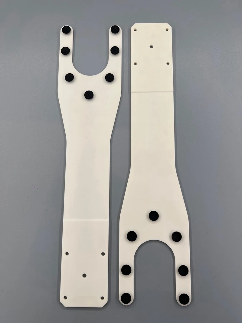
Two 99% alumina wafer end effectors fitted with black rubber vacuum padsRUBBER VACUUM PADS

Rubber pad 3D models for your own design

Our vacuum blades use rubber pads seated in machined recesses, so pad height — and the wafer plane — stays repeatable across a set, and a worn pad is replaced without scrapping the blade.

Designing the blade yourself? We provide 3D models of our rubber vacuum pads to drop straight into your CAD, so the recess is designed around a real part. Anti-static pads at 10⁶–10⁹ Ω·cm volume resistivity are available.

Request the pad 3D models →
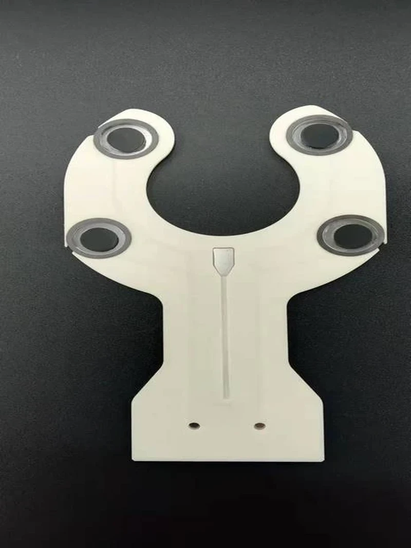
White ceramic Bernoulli wafer end effector with black non-contact Bernoulli padsBERNOULLI DESIGN

Bernoulli blades designed for your wafer

A Bernoulli blade only works when nozzle count, position and air path are balanced — otherwise lift is uneven and a thin wafer bends locally. We design that layout in house and machine the gas channels inside the ceramic body.

Send the wafer, the robot interface and your air supply. The air flow stays adjustable, so the hold can be tuned on your own tool.

▶ See how Bernoulli lift works
BROKEN SAMPLEMEASUREDNEW BLADEREVERSE ENGINEERING

From a new part — or a broken one

No drawing? Send us the blade you are running — a new spare, or one that has already broken. We measure it on our own metrology equipment and rebuild the profile, mounting pattern, vacuum port and pad positions.

We confirm the reconstructed drawing with you before any ceramic is cut, then build the replacement in the material you specify.

Precision Measurement →
HOW A BERNOULLI ARM HANDLES A WAFER

The arm closes the gap. The wafer floats on the film.

A Bernoulli arm works with the wafer above it or below it. Either way it is the white ceramic arm that moves, slowly, and the wafer is held on a thin air film from six paddles — the wafer surface does not touch the blade. Black anti-static PEEK stoppers around the edge keep it centred, and the air flow is adjustable.

WAFER ABOVE THE ARMLift pins raise the wafer; the arm slides in and rises slowlyFLOATS JUST ABOVE THE STEPvacuum chuck with lift pinsEDGE DETAIL · TO SCALEvacuum chuckwaferPEEK stopper ↑paddle ↑white ceramic armWAFER BELOW THE ARMThe arm comes down slowly over the waferHELD JUST BELOW THE ARMporous ceramic vacuum chuckEDGE DETAIL · TO SCALEporous vacuum chuckwaferPEEK stopperpaddlewhite ceramic armwhite ceramic armblack PEEK stopper / paddleair / vacuumSIDE SECTIONS · 300 mm WAFER · MAIN VIEW TO SCALE
1
The arm closes the gap slowlyLift pins raise the wafer just enough for the arm to slide in, then the arm rises slowly. Or the arm comes down slowly over a wafer on the chuck. The wafer does not jump across a gap.
2
The wafer floats on a thin air filmAir comes out of six paddles, level with the stopper step. The wafer is held just above the step, or just below the arm, without touching the blade surface.
3
PEEK stoppers keep it centredBlack anti-static PEEK stoppers at 1, 5, 7 and 11 o'clock form a small arc step, lower than the wafer top. On the chuck side, the wafer is set down and the vacuum chuck takes over.

Tell us the wafer, the robot and the problem. Whether you need a pad 3D model, a Bernoulli design or a copy of a broken blade, send what you have — a drawing, a 3D file, photos or the part itself — and we will come back with a design review before quoting.

SEE IT WORK

Product Videos

How a Bernoulli arm handles a wafer, end effectors we built to drawing, a blade running in production, and how one is made on our own floor.

Bernoulli Wafer Arm — Wafer Above or Below the Arm

A short animation of both Bernoulli modes: the arm closes the gap slowly from below or from above, and the wafer floats on a thin air film without touching the blade. Anti-static PEEK stoppers keep it centred.

ENGINEERING FAQ

Wafer End Effector FAQ

Common questions from equipment builders, refurbishers and fab engineers specifying a replacement or custom blade.

01

What is a ceramic end effector?

A ceramic end effector is the blade or fork at the tip of a wafer transfer robot, made from technical ceramic — alumina, silicon carbide or anti-static ceramic — instead of metal or plastic. It is the only part of the robot that touches the wafer, so it defines how the wafer is held (vacuum, edge grip, friction pad or a non-contact Bernoulli air film) and largely determines particles, placement repeatability and breakage. “Wafer end effector” is the general name; a ceramic end effector is the version chosen when stiffness, cleanliness and heat matter.

02

Why use a ceramic end effector instead of metal?

Because no bare metal touches the wafer, and the blade stays stiff, flat and stable when hot. Our 99% alumina has a Young's modulus of 360 GPa and our SiC 430–440 GPa, so a thin 300 mm blade droops less at full extension and stays clear of the slot below. Ceramic does not outgas, its dense surface sheds far fewer particles than a coated or anodised metal blade, and our ceramic paddles are used at up to 400 °C. Metal blades remain reasonable for short-reach, cold, non-critical handling.

Ceramic vs metal at a glance →

03

Which ceramic materials are used for wafer end effectors?

Mainly three. Alumina (99% or 99.5%) is the best value for 150/200 mm and moderate 300 mm reach, and is electrically insulating (>10¹⁴ Ω·cm). Silicon carbide (99.8%) gives the highest stiffness and thermal performance for long 300 mm blades and hot-wafer transfer — note that SiC is not an insulator. Anti-Static Ceramic is specified when the blade must sit in a 10⁶–10⁹ Ω·cm dissipative window for ESD-sensitive devices. We sinter our own ceramics in house.

Alumina material page →   Silicon Carbide (SiC) material page →

04

Do you make vacuum-groove or porous ceramic end effectors?

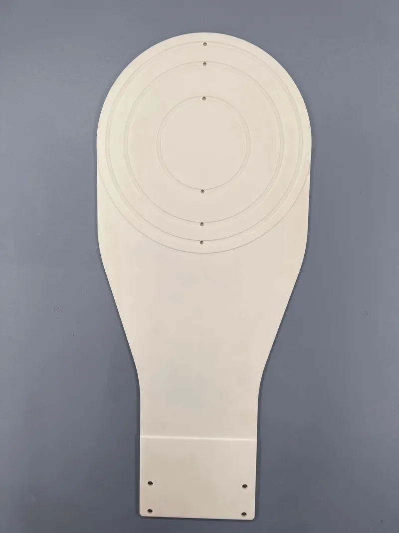
Vacuum-groove blades, yes: grooves, holding holes and concentric rings are machined into the blade face, or our snap-in rubber vacuum cups are fitted instead of grooves. For porous ceramic, we make porous ceramic vacuum chucks in house, so a porous vacuum area in a blade can be reviewed for your wafer — send the drawing and we confirm feasibility before quoting.

Porous Ceramic material page →

05

Which wafer sizes do you support?

150, 200 and 300 mm wafers (6, 8 and 12-inch), including 300 mm framed wafers. 100 mm, 450 mm and panel formats are made on request, and extra-large ring, fork and paddle blades are built to drawing.

06

Can you make an end effector from my drawing?

Yes — most of our end effectors are built to the customer's drawing. Send a 2D/3D file; every drawing is reviewed before machining and critical dimensions are 100% inspected. No drawing? Send the blade you are running — a new spare or a broken one — and we measure it, reconstruct the drawing and confirm it with you before cutting material.

OEM & ODM services →

07

Should I choose a vacuum, edge-grip or Bernoulli end effector?

It depends on what the wafer back side allows. Vacuum blades give the strongest hold and the fastest motion, but touch the back side and need a vacuum line. Edge-grip forks touch only the bevel, which suits patterned or bonded back sides and vacuum environments. Friction-pad blades are the simple, robust choice inside vacuum transfer modules and hot chambers. Bernoulli blades do not touch the wafer surface and suit very thin, warped or fragile substrates.

Try the end effector selector →

08

Does a Bernoulli end effector touch the wafer?

No — the wafer surface does not touch the blade. Whether the wafer sits above the arm or below it, the arm closes the gap slowly and the wafer is held on a thin air film created by the nozzles. Anti-static PEEK stoppers around the edge keep it centred, and the air flow is adjustable, so the holding force is tuned to the wafer and to the robot motion.

We design the nozzle layout and air path in house, and our ceramic paddles can be used at up to 400 °C.

How Bernoulli lift works →

09

Can you supply 3D models of the rubber vacuum pads?

Yes. Our snap-in vacuum cups ESD-ND-11, ESD-ND-12 and ESD-ND-15 can be downloaded as STEP models from the cup table on this page, so you can place them in your CAD and design the blade around a real part. Anti-static pads with a volume resistivity of 10⁶–10⁹ Ω·cm are also available.

Vacuum cup table and STEP downloads →

10

Do you supply ESD-safe or anti-static end effectors?

Yes, three ways. A bulk Anti-Static Ceramic body with a volume resistivity of 10⁶–10⁹ Ω·cm — nothing to wear through, so it holds its window at high cycle rates. An ESD coating on alumina with a surface resistance of 10⁶–10⁹ Ω at lower cost. And anti-static rubber vacuum pads at 10⁶–10⁹ Ω·cm. Tell us your resistivity window, cycle rate and temperature and we recommend the route.

Anti-Static Ceramic (ATC) material page →

11

What is the minimum order quantity and lead time?

We accept single-piece prototypes and small replacement batches as well as production quantities. Lead time depends on material, blade size and whether tooling is needed; send the drawing or sample and we confirm a schedule with the quotation.

OEM & ODM services →

12

What information do you need to quote a wafer end effector?

Ideally: wafer size and material; handling method; reach and cassette slot pitch; maximum blade thickness; robot wrist mounting pattern; operating temperature and atmosphere; any ESD or particle specification — and for a Bernoulli blade, your air supply. A 2D/3D file or a physical sample covers most of this in one step.

Also Known As

Buyers and equipment engineers ask for this part under many names. A LONGYI wafer end effector is the same component described as:

Wafer End EffectorWafer Handling End EffectorWafer BladeWafer ForkRobot BladeWafer PaddleCeramic End EffectorCeramic Wafer Handling BladeEFEM End EffectorVacuum End EffectorEdge Grip End EffectorBernoulli WandBernoulli GripperWafer Pick-Up Arm TipAlumina End EffectorSiC End EffectorESD Safe Wafer Blade

If the drawing in front of you uses a different term, send it over — the part is almost certainly one we build.

ALSO NEED TO HOLD THE WAFERS YOU MOVE?

Porous Ceramic Vacuum Chucks

The wafers your end effector transfers still have to be held flat for grinding, dicing, laser processing and inspection. LONGYI manufactures porous ceramic vacuum chucks in house — one precision-ceramic partner for both handling and holding.

Explore Porous Ceramic Vacuum Chucks →
CONTACT LONGYI ENGINEERING

Have a Drawing — or a Broken Blade — to Replace?

Send it to our engineers. We review the wafer, the robot and the environment, recommend the handling method and material, and quote — prototypes from one piece.

To quote quickly, send us:
2D/3D drawing — or the blade itself, new or brokenWafer size, material, thickness and bowHandling method, reach and cassette slot pitchOperating temperature, atmosphere and ESD requirementRobot wrist pattern — and air supply for a Bernoulli blade

Contact Us

Contact Form EN 2026
Skip to toolbar
➤