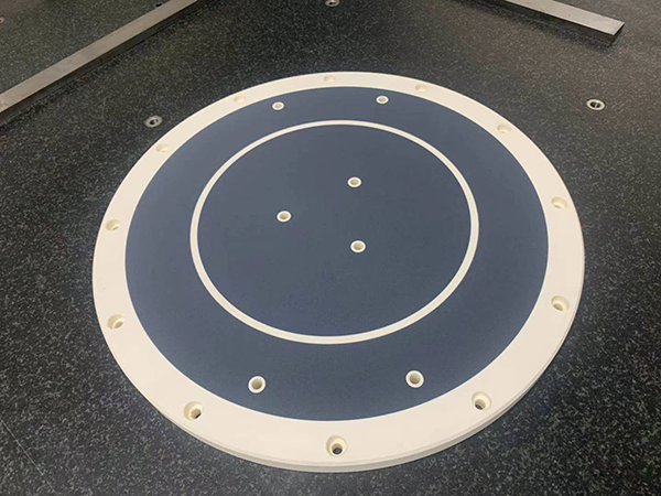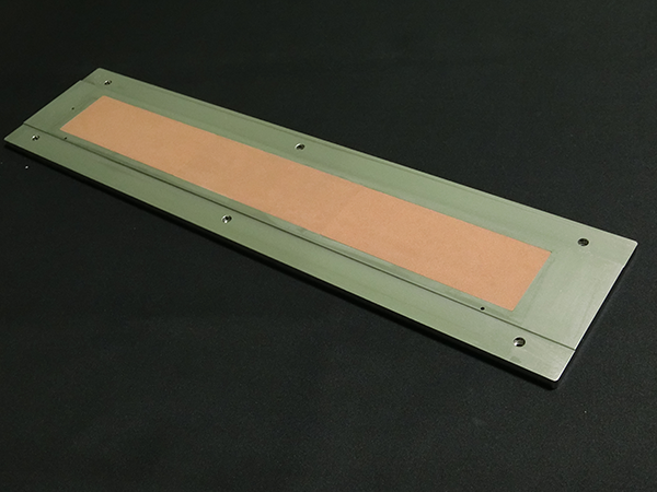
Porous Ceramic Vacuum Chuck

LONGYI · POROUS CERAMIC WORKHOLDING · MADE IN TAIWAN

Porous Ceramic Vacuum Chuck Tables for Wafer, Glass & Precision Substrates

LONGYI Precision Technology manufactures porous ceramic vacuum chucks in-house — from the porous ceramic itself to the lapped, measured chuck table. Vacuum is drawn evenly through the whole surface, so thin wafers, glass panels and FOPLP substrates are held flat without groove marks.

QUICK ANSWER

A porous ceramic vacuum chuck holds thin, fragile or non-magnetic substrates through evenly distributed micro-pore suction instead of grooves or drilled holes — flatness down to 2 μm, with no localized suction marks.

HOW A POROUS CHUCK HOLDS A WAFERCROSS-SECTION
1Wafer placed — air is drawn down through the open micro-pores. 2Pores sealed by the wafer — vacuum pulls it flat. 3Held flat by uniform suction across the whole surface.
SCROLL
2 μmFlatness, from
3 μmParallelism, from
2–100 μmPore Size Options
40–45%Porosity
1200×800Max. Assembly (mm)
Wafer Back GrindingWafer DicingLaser ProcessingAOI InspectionFOPLP PanelsMEMSProbe CardThin Glass HandlingPrecision MetrologyBattery & Copper Film
THE CONCEPT

Hold the Whole Surface, Not Just the Grooves

Watch the same thin part go onto two chucks. A grooved or drilled chuck pulls only where there is a hole — and pulls the substrate slightly into each one. A porous ceramic chuck pulls through every micro-pore at once — which is why it is the standard for thin wafers and polished glass.

1 · THIN PART PLACED 2 · VACUUM ON — PULLS AT HOLES ONLY 3 · A DIMPLE AT EVERY HOLE VACUUM CHAMBER MAGNIFIED GROOVED / DRILLED CHUCK

Suction concentrated at holes and grooves

Cheaper to make and fine for rigid parts. The part lies flat on the surface, but every hole pulls it slightly down into the opening — and only there. On thin or soft substrates those dimples can print through into a ground or polished surface, and one blocked hole loses the hold at that point.

1 · THE SAME THIN PART PLACED 2 · VACUUM ON — PULLS THROUGH EVERY PORE 3 · HELD FLAT — NO DIMPLE VACUUM CHAMBER MAGNIFIED POROUS CERAMIC CHUCK

Suction spread across the full contact area

Thousands of interconnected micro-pores carry the vacuum, so the substrate is supported everywhere and there is no open hole for it to be pulled into. The one rule: keep the surface clean, because contamination that fills the pores reduces flow.

SPECIFYING A CHUCK · FIVE DECISIONS

How We Define Your Chuck Table

Scroll through the five decisions our engineers work through with you before any ceramic is cut.

Substrate & Process

What sits on the chuck, how thick it is, how much it bows, and what happens to it — grinding, dicing, laser or inspection. Everything else follows from this.

Wafer · Glass · FOPLP · Film

Pore Size

Fine pores give a smoother surface and less dimple transfer into thin or soft substrates; coarse pores flow more air and tolerate partial coverage. It is a trade-off, not a quality grade.

2 / 5 / 10 / 15 / 30 / 50 / 100 μmPorous Ceramic (PC) →

Material: Standard or Anti-Static

Standard porous ceramic for rigidity and uniform hold; anti-static ceramic with controlled resistivity when charge must bleed away from sensitive devices.

ESD 10⁶–10⁹ ΩAnti-Static Ceramic (ATC) →

Vacuum Zoning & Flow

Concentric zones for multiple wafer sizes, high-flow ports for warped parts, and a working flow range so you can size the vacuum source correctly.

Typical 40–100 L/min

Flatness & Verification

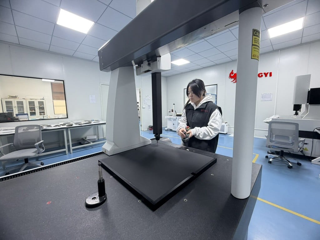
The surface is ground after the porous ceramic is joined to its base, then every critical dimension is measured before the chuck ships — flatness is always quoted against size.
From 2 μm · 100% critical dimsPrecision Measurement →
LONGYI quality technician measuring chuck flatness on a bridge-type CMM
LONGYI quality technician measuring chuck flatness on a bridge-type CMM 01 / 05
MATERIAL OPTIONS

Two Porous Ceramics, One Decision: Does Charge Matter?

Both are engineered in our own plant for semiconductor, glass, optics and FOPLP work holding. The choice usually comes down to whether your devices are sensitive to electrostatic discharge.

MaterialKey CharacteristicBest Suited For
Porous Ceramic (PC)Uniform microporous structure, high rigidityWafer inspection, dicing, laser processing, measurement
Anti-Static Ceramic (ATC)Controlled resistivity, 10⁶–10⁹ Ω ESD performanceCleanroom automation, wafer transfer, ESD-sensitive processes

Why Choose LONGYI Materials?

Uniform vacuum distribution for precision workholdingHigh flatness and dimensional stabilityOptional anti-static (ESD) performance from 10⁶–10⁹ ΩCustom pore sizes and vacuum zone configurationsSuitable for semiconductor, glass, optics, FOPLP and precision automationOEM and ODM engineering support
DESIGNING YOUR OWN CHUCK

Custom Chuck Design Guidelines

Drawing the chuck yourself? Keep to these limits and your model can go straight to engineering review — no redesign loop.

01

Size & Layer Build-up

How thin the chuck really is — and what each layer does.

260 × 260 mm CHUCK · DRAWN TO SCALE260 mm260 mm15 mmthickPorous ceramic suction areaalumina frame rim only 3 mmDETAIL · EDGE AT THE SIDE PORT, 12× ENLARGEDPorous ceramic 4–5 mm▲ Vacuum chamber 1 mmAlumina base 9–10 mmPT 1/8Ø ≈ 9.7Hex ≈ 121515 mm TOTAL = ROOM FOR THE PT 1/8 FITTING HEX
Porous ceramic layer4–5 mm
Vacuum chamber1 mm
Alumina below chamber9–10 mm
Total (side port)15 mm
Frame rim≥ 3 mm
02

Machined Features

Limits for threads, pins and holes in the ceramic body.

ThreadsM2.0 min.
Dowel pin holesØ3.0 mm +0.02
Hole-to-hole spacing≥ 10 mm
Hole depthBlind — not into the vacuum chamber
03

Vacuum Port, Flow & Thickness

Where the port goes decides how thick the chuck must be — and how much air it can move.

ThreadPT 1/8 (Ø ≈ 9.7 mm)
Fitting hex≈ 12 mm
Quantity1–2, set by zoning
PositionSide (15 mm) or bottom (12 mm)
OPTION A · SIDE PORT15PT 1/8Hex ≈ 12• Thread sits in the side face → 15 mm thick• Rim widens where the port enters✓ No access needed under the chuckOPTION B · BOTTOM PORT12Port in the underside✓ Thickness no longer set by the fitting → 12 mm✓ Port size not limited by the side face• Table or plate needs clearance for the fitting

We size by flow, not vacuum level

Few users seal the surface with film the way semiconductor lines do. Most want one chuck to hold parts of every size, so part of the porous surface is always left open and air leaks in there. The chuck that holds best is the one that moves the most air.

Bigger port = more flow = better hold

With the same vacuum source, a 9 mm port moves far more air than a 1 mm hole. More flow pulls a warped part down fast and keeps small parts held even when most of the surface is uncovered.

How to choose

One chuck for many part sizes → go for flow: a large port, on the side (15 mm) or underneath (12 mm).Smaller port or thinner side face → less flow; best when the part covers most of the surface.
04

Frame Material: Alumina, Not Aluminium

Recommended whenever flatness is critical.

✓ Alumina frameHolds its flatness long-term.A knock at worst chips an edge — the surface does not deform.
✗ Aluminium frameDents on impact, and the dent shows up in flatness.Repair is difficult once it is deformed.
05

Lightweighting Pockets

Draw the pockets you want directly in your model.

For how we place pockets without losing stiffness, see Lightweighting under Design Options.

06Designing your own chuck? Send us your model/drawing for review and quotation.
3D model or 2D drawing — outline, threads, pin holes, vacuum ports, pocketsWorkpiece: material, size, thicknessFlatness requirementQuantity
Send Your Drawing →
Not sure which material is right for your application?

Our engineering team recommends the porous ceramic solution from your substrate material, vacuum system, flatness requirement and production process.

Request an Engineering Review →
ENGINEERED FOR DIFFICULT PARTS

Design Options When a Flat Porous Surface Isn't Enough

Each of these exists because a real part on a real machine would not behave otherwise.

Porous ceramic vacuum chuck with drilled vacuum holes for two-stage clamping of warped partsTWO-STAGE CLAMPING

Drilled holes + porous ceramic for badly warped parts

A porous surface cannot pull down a part that starts far off the surface — the open gap simply leaks, and raising vacuum makes no difference: the chuck runs out of flow, not pressure. So we drill through-holes in the porous layer, like a conventional vacuum chuck, and feed them from a separate high-flow line.

Stage one uses the large holes to draw the warped part down. Once it is seated, the supply switches to the porous ceramic, which holds it flat with suction spread across the whole contact area — instead of pulling the material slightly into each hole the way a hole-only chuck does.

▶ Watch how two-stage clamping works
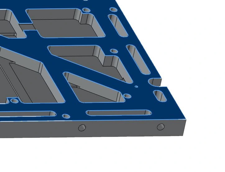
Underside of a porous ceramic vacuum chuck base with machined pockets reducing contact areaRELIEVED UNDERSIDE

Less contact area underneath — easier to grind flat

A chuck that seats on its whole underside is at the mercy of every particle on the machine table: one piece of swarf under a large flat face tilts the whole assembly, and the error goes straight into the working surface above it.

So the underside is relieved and only a defined contact land touches the table. Less area to grind means that land comes out flatter and more consistent than a full face, there are fewer places for a particle to sit, and the chuck seats the same way every time it goes back on the grinder.
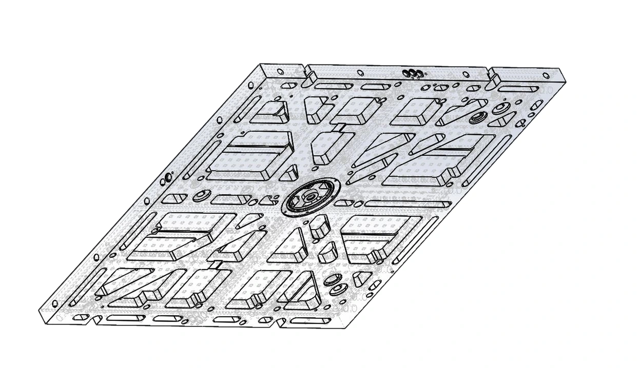
Porous ceramic vacuum chuck base frame with machined lightweighting pocketsLIGHTWEIGHTING

Pockets machined into the base frame

Base frames get heavy quickly as the footprint grows, and mass matters wherever the chuck moves, sits on a load-limited table, or is lifted by hand during changeover.

Material is removed from the low-stress zones of the frame while the section depth stays intact. Bending stiffness comes mostly from that depth, so the pockets cut weight without letting the chuck sag under vacuum load. Pocket layout is worked out per part, not copied between sizes.

HOW TWO-STAGE CLAMPING WORKS

Large holes pull the part down. Porous ceramic holds it flat.

One chuck, two separate vacuum circuits. Drilled through-holes run to their own high-flow line (A); the porous ceramic sits over its own vacuum chamber on a second line (B). Each does the job the other cannot.

STEP 1 · A BADLY WARPED PART IS PLACED STEP 2 · LINE A ON — LARGE HOLES PULL IT DOWN STEP 3 · LINE B ON — POROUS CERAMIC HOLDS IT FLAT VALVE A VALVE B LINE A · HIGH-FLOW → HOLES LINE B · VACUUM → PORES POROUS CERAMIC PORE VACUUM CHAMBER HOLE MANIFOLD (SEPARATE) BASE FRAME Drilled through-hole GAP · AIR LEAKS IN PORES ALONE CAN'T PULL IT HELD FLAT ✓NO DIMPLE AT THE HOLES
  1. 1
    A badly warped part is placedIts edges sit far above the surface. Air leaks in through the gap, so the pores alone cannot build enough pull — raising vacuum doesn't help, the chuck runs out of flow.
  2. 2
    Stage 1 · Line A pulls it downThe large drilled holes on the high-flow line move a lot of air fast and drag the raised areas down onto the ceramic surface.
  3. 3
    Stage 2 · Line B holds it flatOnce the part is seated, vacuum switches to the porous ceramic. Suction spread across the whole contact area holds it flat — without pulling the material into each hole the way a hole-only chuck does.

None of these are catalogue options. Which ones a chuck needs depends on the substrate's starting bow, what the table will carry, and how clean the environment really is. Send us the substrate, the machine and the problem you are having — we will tell you which apply before quoting.

SEE IT WORK

Filmed on Real Equipment

Including one clip where the customer — not us — does the measuring.

How a Porous Ceramic Vacuum Chuck Works

The same surface does two opposite jobs. Draw air in and the workpiece is held down; push air out and it lifts clear on a film of air. Filmed on copper sheet and battery film.

ENGINEERING FAQ

Porous Ceramic Chuck Table FAQ

The questions dicing, grinding, laser and inspection engineers ask most often when specifying a new or replacement chuck table.

01

What is a porous ceramic chuck table?

It is the vacuum work-holding surface a wafer, glass panel or thin substrate sits on during dicing, grinding, lapping and inspection — a single piece of open-pore ceramic instead of a metal plate with drilled holes or machined grooves, so vacuum is drawn evenly through the whole surface.

Because suction is distributed rather than concentrated, the part stays flat enough for thin wafer grinding and clean enough for dicing, where a single groove imprint can shift the kerf.

02

Is a chuck table the same as a porous ceramic vacuum chuck?

Yes. "Chuck table" is the term in equipment part lists and service manuals; "porous ceramic vacuum chuck" is the term used by component suppliers. Engineers also say porous chuck, vacuum chuck or wafer chuck — all the same open-pore ceramic work-holding surface, and LONGYI manufactures all of them.

Porous Ceramic (PC) material page →

03

When is a porous ceramic vacuum chuck the best choice?

When you need to hold a thin, fragile or highly flat substrate without suction marks — wafer inspection, dicing, laser processing, thin-glass handling and precision metrology. Because vacuum is spread evenly through thousands of micro-pores, the whole surface is supported and can be held flat from about 2 μm — which grooved or single-hole chucks cannot match.

04

What pore size should I specify?

We supply 2 to 100 μm at 40–45% porosity. Fine pores give a smoother surface and less dimple transfer but flow less air; coarse pores flow more and tolerate partial coverage but can print into thin films.

Starting point: fine pore for thin wafer grinding, polished glass and film-coated substrates; coarse pore for dicing frames, saw-cut parts and tables the workpiece does not fully cover. Tell us the substrate, thickness and coverage and we will propose a structure.

05

How flat can a porous ceramic chuck table be made?

Flatness from 2 μm and parallelism from 3 μm — always quoted against size, because a large table cannot hold the same absolute value as a small one. The surface is ground after the porous ceramic is joined to its base. Asking for one number across every size is the most common specification mistake we see. Maximum assembly size is 1200 × 800 mm — send the dimensions and the flatness your process is measured against, and we will confirm what is achievable before quoting.

06

How do you handle a warped or bowed substrate?

The key is airflow, not peak vacuum. A larger open-pore area and higher flow pull the bowed material down; raising vacuum on a low-flow chuck often just leaks at the gap. We select pore size and porosity to give enough flow for your substrate, and for severe bow we add drilled high-flow holes for two-stage clamping. Tell us the material, thickness and how much bow you start with.

07

What suction flow rate does the chuck need?

Typically 40 to 100 L/min, depending on chuck size, pore grade and how much surface is exposed. Larger chucks and coarser pores need more flow. We specify the working range for your configuration so you can size the vacuum source correctly, rather than discovering it on the machine.

08

How do we choose the right vacuum source?

Match the pump to both vacuum level and flow. Fine-pore chucks reach high vacuum at modest flow; coarse-pore and large chucks need sustained higher flow. A vacuum pump suits continuous holding; a venturi or ejector is convenient where compressed air is already available. Tell us your substrate and cycle and we will recommend a suitable source.

09

Do you make ESD or anti-static porous chuck tables?

Yes — anti-static ceramic with a controlled surface resistivity of 10⁶–10⁹ Ω, so charge bleeds away instead of accumulating under the substrate. Specify the resistivity window your fab works to rather than just "anti-static" — the term covers several orders of magnitude.

Anti-Static Ceramic (ATC) material page →

10

How does it compare with a grooved or drilled vacuum chuck?

A grooved or drilled chuck applies vacuum only at its holes and grooves — cheaper and fine for rigid parts, but thin substrates are pulled slightly into each opening and the pattern can print through. A porous chuck spreads vacuum across the full contact area; the trade-off is that the surface must be kept clean.

11

Can you build a chuck table from my drawing, or copy an existing one?

Both. We manufacture to a 2D or 3D drawing, and we can reproduce a chuck table from an existing part when no drawing survives — measuring diameter, thickness, mounting interface, vacuum port and porous area, then confirming the reconstruction with you before cutting material. A worn or damaged table is replaced with a newly manufactured one built to the measured original.

OEM & ODM capability →

PDF

Porous Ceramic Vacuum Chuck Catalog

The whole chuck family in one 8-page catalog — specifications, standard models and selection guidance for engineering teams.

Wafer Grinding, Wafer Work, Work Holding & Dicing chucksStandard models & key specificationsPC / ATC material options & pore size guideApplication & selection guideCustom design, maintenance & rework
Format: PDF8 pagesLanguage: EnglishRev. 2026.10
↓ Download Catalog (PDF)

C-PRO-GB Work Holding detailed catalog (PDF) →

Also Known As

Depending on the industry, equipment manufacturer or production process, the same porous ceramic workholding technology — used for precision vacuum holding and air-floating applications — goes by several names:

Porous Ceramic Vacuum ChuckPorous Vacuum ChuckCeramic Vacuum ChuckWafer Vacuum ChuckChuck TablePorous Ceramic TablePorous Ceramic PlatformNegative-Pressure Vacuum Suction Table
ALSO NEED TO MOVE THE WAFERS YOU HOLD?

Custom Ceramic Wafer End Effectors

The wafers your porous ceramic chuck holds still have to be transferred across the tool. LONGYI machines ceramic wafer end effectors to your drawing in Alumina (Al₂O₃), Silicon Carbide (SiC) and anti-static ceramic — with the rigidity, low outgassing and static dissipation metal end effectors struggle to hold. One precision-ceramic partner for both holding and handling.

Explore Wafer End Effectors →
CONTACT LONGYI ENGINEERING

Have a Drawing or a Worn Chuck to Replace?

Send it to our engineers — we review the substrate and the machine, recommend pore size and material, and quote. A worn chuck with no drawing is fine: we can measure and rebuild it.

To quote quickly, send us:
2D/3D drawing — or photos and key dimensions of the existing chuckSubstrate material, size, thickness and starting bowProcess and machine model (grinding, dicing, laser, AOI…)Required flatness and the size it applies overESD requirement and quantity

Contact Us

Contact Form EN 2026
➤